Since my last post I have learned a lot about RC equipment and testing. This has led me to realize that I need another servo tester, or power analyzer. This one does not control the server under test, but reports on the servo voltage and current use. This is very important in making sure that servos are up to the task at hand and that the battery or BEC circuit is capable as well.
You may have seen one of my previous posts about my big T28 Trojan and my crash. I suspected that this crash was due to power issues but have had no way to test this. With this servo power analyzer I will be able to find out what is going on with the servo/receiver power system.
What is needed for this tester is a way to measure amps and voltage used by a servo, and all the way up to all servos including the receiver.
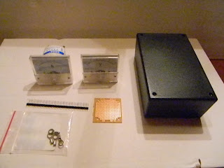
These are the parts that will be used build my servo power analyzer.
The way I plan on using this to test my T28 setup, is to plug the BEC into the input side and the receiver with all of the servo connections into the output side. Then I will monitor for voltage fluctuations (anything dropping much below 6V) and maximum amp flow. Anything above the amp rating of the BEC will be a sign that it is not up to the task or I have a problem with a servo or two.
I realize that I did not include a circuit diagram and this would be very helpful for anyone wanting to make one of these. It's really very basic and should be easy to duplicate. So, here it is:
The positive voltage path flows through the Amp meter. The voltage is measured the positive and negative voltage paths. The servo signal wire passes straight through without interruption.
Thanks for stopping by my blog. Please feel free to post comments, good or bad, and be sure to come back and check for future posts.


