Pages

Showing posts with label brushless. Show all posts

Wednesday, November 29, 2017

Buzzard Bombshell Electric Conversion and Mods

About a year and a half ago I picked up this wonderful high wing balsa old timer at a swap meet.  I did not know what it was but I'm a sucker for an inexpensive balsa old timer, especially a three channel high wing.  He wanted $25.  I offered $15.  He threw in a motor, esc, and two servos and we settled for the $25 he was asking!  I was a happy camper.

After some time and a bunch of Internet searching, I finally discovered that what I had bought was a plane called the Buzzard Bombshell.  The original design was done and built by Joe Konefes in 1940  with about a 72 inch wing span.  It was intended as a free flight as RC gear was way too expensive for most people.  This plane was designed to head up as high as so many ounces of fuel would take it and then glide for as long as possible (Joe flew his for over 49 minutes at the 1940 NATS).  To help with extended glide times they incorporated large tail surfaces that helped with lift and moved the CG to 50% or more back from the leading edge.  With the heavy motors of the time, this made for an interesting stubby nose look.

Mine was a more current and smaller version that was intended for 1/2A power sources.  It looks like it was setup for a Cox .049 judging from the mounting holes in the firewall.  Now by smaller I mean about a 45 inch wing span and still a good size plane.


Didn't realize that these cluttered photos were the only ones that I had at the time I posted this.


I'll take some better ones as soon as I get some time.

A couple of things that I really liked about this plane is that the builder did a pretty good job of construction and covering, but also, I see no oil residue and so don't think that a motor was run on this plane let alone even mounted.  I don't think it has ever been flown.

The first thing I looked at doing was to figure a motor mount


You can see here the holes for the original motor mount.  Fortunately the builder install blind nuts from the back side.  I just needed to figure out what size they are and how to go about using them.  They are oddly laid out so I can't directly use them and I'll need an adapter.


You can see the blind nuts in this photo.


I decided to use a circle of 1/8 inch plywood.  I would drill holes to line up with the engine mount holes and then drill holes to fit the electric motor mount.


I lined up the disk from the back side so that I could transfer the mounting holes from the front side.


Here is what I came up with.  I started counter sinking the holes so that I could use flat head screws so that it will fit flush against the firewall.


Here are the parts that I came up with to create my motor mount.  I ordered some aluminum stand offs from an online source and screws and washers from my local hardware store.  As I recall all of the threads turned out to be a standard 10-24.


Here is how the stand offs will fit with the electric motor x mount and the original motor mount.


This is how it would look with the longer stand offs.


Here is the new round plywood mount test fitted in place.


I needed to ream out the x mount slightly to fit the new screws.


Now the screws fit fine.


Here are the different stand offs and screws that I used.


Here is how it would look with the long stand offs.


This is how it would look with the short stand offs.  I like this look better, it puts the propeller closer to where it would have been with the originally designed gas motor.


I used different amounts of washers behind the x mount arms to set down and left thrust angles.


Here is the end result.

Now I need to start looking at where and how to mount the battery, ESC, and the two servos before I can get this thing back in the air.  These will be done in future updates.

Thanks for stopping by my blog.  Please feel free to post comments, good or bad, and be sure to come back and check for future posts.

$5 Durifly Ryan STA(M)

Ok, maybe it will not turn out to be $5, but it started that way.  I was browsing Hobby Kings bargain bin items and under the $0.99 bin I found all of the critical parts for the Durifly Ryan STA(M)!  I was really bummed to find out that the engine cowling and parts kits, while not $0.99, were out of stock, but I can live without those.  I'm not so much looking for a complete, complete deal here, I just want something that I can have fun flying, looks reasonably good, and relatively cheep.

So, here is what I ordered.  One set (yes, set, right and left) of wings, one fuselage, one cockpit, one rudder, and one stabilizer.  Each was only $0.99!  So, ok, this will not come out to a $5 build as I did have to pay shipping and HK is smart enough not to let you order too many $0.99 pieces without ordering something else (I had to split this into two orders!), so shipping cost me about $28, or about $14 each order.  But still, I'm only about $35 into a $150 plane, so far.

I did already add two 9g servos to the wings (about $4 each).  You can see them installed into the wings in these photos.


The really good stuff (besides the parts being CHEAP!) is that everything was already covered, all movable surfaces were already hinged with control horns and stoppers, and the rudder has the tail wheel installed.  All very nice indeed!

The not so good stuff, the wings came without the spare (that seemed really odd!).  So I had to make one using a lot of educated guessing (but I got it done).  The rudder was a little kinked about mid way, right where the balsa color changes.  I have no engine cowl.  I have no landing gear, wheels, or pants (I'll make a set but don't plan on making the pants), the cockpit section came without the dash decals, the manual (as sparse as it was) is no longer available (luckily someone posted photos of theirs on RCGroups), and the hardware kit is no longer available (this included all of the linkage, screws, support wires/string, wing mounting screws, and misc. hardware).  I will also have to provide two more servos for the tail surfaces, a 25Amp ESC, a 3530 1100Kv motor, and a 10x6 prop.

So far I have the wing spar made, the wing halves epoxied together, and the aileron servos installed.
This photo shows the wing spar that I cut from 1/8 inch plywood.  I measured the depth of the slot in each wing to come up with an estimate for it's length.  I measured the angle of the wing roots to come up with an approximate dihedral angle.  I carved and sanded until it fit and the two wing roots came together nice and flush.


I then put a liberal amount of 5 min. epoxy into each wing root spar opening and covered the root faces with a thing layer of epoxy.  Then I slid the left side of the spar (yes, it has sides to match the wing) into the left wing and then slid on the right wing onto the right side.  Then I taped up the bottom side good and flush (lower photo) and then pulled the top side together nice and flush and secured with tape (upper photo).  I left this to sit over night.


Here is what the parts look like so far.

Check back again and find out how this new project is coming together and as usual, thanks for stopping by my blog.

Please feel free to post comments, good or bad, and be sure to come back and check for future posts.

Sunday, October 1, 2017

Cleaning a Dirty Brushless Motor

Some times you biff a plane into the dirt.  Some people tend to do this a lot more than others.  I think I tend to land (pun intended) into that group.  This can really mess up an electric motor, especially if you keep trying to spin the propeller (if one still exists), or the shaft.  This can cause all kinds of damage to the magnets and stater coils.  So don't do it!  If you get dirt into your motor, just leave it until you get home and can clean it.  Brushless out runner electric motors are actually quite easy to clean out.

I recently had this issue with my Hobby King Club Trainer.  I came in over a freshly plowed field and didn't make the runway.  Of course it nosed over and the cowling scooped a large amount of dirt all around the motor.

Below is how I went about cleaning it up and getting it back into shape.

The first thing that I did was to take the nose cone and prop off.  All the while being careful not to spin the motor shaft (or at least as little as possible).  Then I removed the motor from it's mount and disconnected the power connectors.

Now you need to take the motor apart and separate the out runner and magnets from the stater coils.  A lot of times this is done by removing some Allen set screws.  In my case, this was held together with an "E" clip in a slot on the end of the shaft.  There are special tools for removing these, but I usually just use a small screw driver or pick.  Just be careful not to bend or gouge up this little item or you will need to find another.


Now separate the two parts.  This is not always easy to do as the strong magnets used will try to keep the iron stater where it is.  Just be careful and don't pull on the wires!  For mine, I was able to pull on the prop shaft and the bearing tube.  After some effort, it popped right apart.  Depending on how much dirt is in your motor it may cause it to bind up.  If this happens, first try tapping the motor with the bell facing down to see if anything will come out.  Then try to gently turn the motor just enough to free it up.  Repeat this process as needed until it can be taken apart without damage to the magnets or iron stater.


Now take the bell out runner side and tap it down on a suitable surface.  By a suitable surface, I mean something relatively soft.  Don't do this on a hard surface like tile or metal as you risk damaging your tile and the shaft.  This will dislodge most, if not all, of the non magnetic dirt.


Now take a stiff epoxy brush and start bushing out the rest of the bits that remain.  I thought I would have a tough time with the magnetic bits and iron dust with such strong magnets, but they came out quite easily.


As you can see, it's nice and clean once again with no remaining bits.


Now just reverse the process to put things back together.  Be careful putting the stater back into the out runner bell as it can come together quite violently and pinch fingers!  Once it's back together make sure that it spins freely again.  Of course you will still get the "coging" of the magnets and stater, but there should not be any grinding or gritty feel.  If you do encounter this, start over and clean it out again.

Argh!!! It happened again!


You can see that the mud actually mushed all the way through the motor.  I pulled everything apart and used some water to rinse most of the mud off.  Then I made sure that it was dried out to make sure it did not rust and then used these techniques to clean it out the rest of the way.  And yes, it did fly again.

Thanks for stopping by my blog.  Please feel free to post comments, good or bad, and be sure to come back and check for future posts.

Wednesday, November 2, 2016

Foamy Rehab 2

Part II

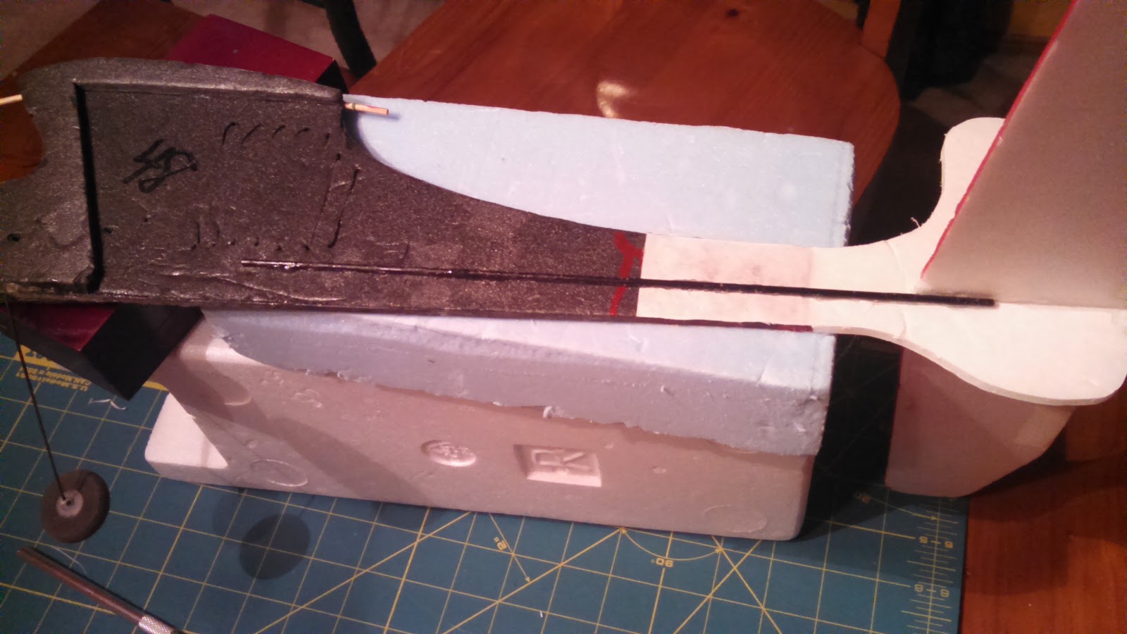
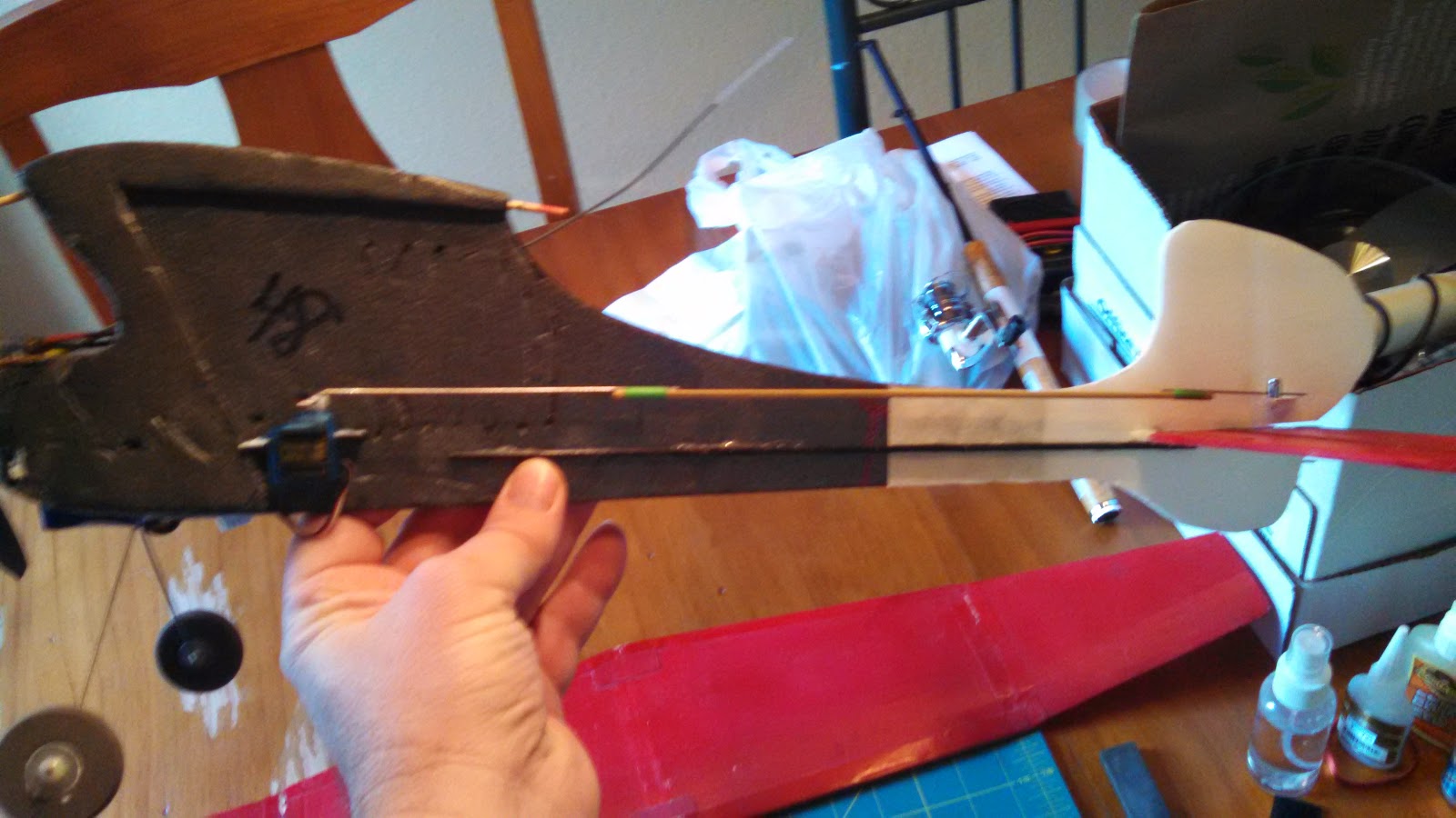
At this point, the carbon rod spar was glued back in place on the opposite side of where it was originally as this surface was clean and flat.  Instead of the brittle epoxy, I opted for Foam Tac which will be more flexible on top of being easier to use.

With the adding back of the carbon fiber spar, the frame reconstruction of this little plane is complete.

Now on to the control surfaces and electronics.

On the left in the photo below are the old servos that came with it.  They were a weird mix and I did not want to rely on them.  I happen to have two new 4g servos on hand and decided to swap them out.


Here is a photo showing the ESC and old servos again.  Note the micro connectors.


This photo shows the size difference in the connectors.  They are much smaller but I was not going to be able to use the 72MHz mircro receiver that came with it (I sold this receiver along with another on Ebay for about $20!).


Here is the new 4 channel receiver that I will be using with the two new micro servos installed.  The old ESC still has the micro connector.  I'll have to replace this connector as I don't want to replace this ESC as it already has all of the other connectors soldered on and I would have to get these as well.

OK, on to the tail surface repairs that I decided to make as well as changes to the control horn installs.

There were some dings in the leading edge of the stabilizer that I fixed by applying Gorilla glue and then covering with masking tape.  I let the glue foam up and then trimmed and sanded to shape.


I removed the elevator so that I could redo the hinge tape (pretty much rotted apart) and install a new control horn.  You can see here that the rudder just uses the paper on one side of the foam board for the hinge.

Here I'm cutting pieces from a plastic card to make the parts I need.  I kind of played with the shapes until I was satisfied.

I used this method (Ed from Experimental Airlines, thanks) where it glues on one side and penetrates to the other.  This makes for a light but solid horn.  I cant remember if I used hot glue or Foam Tac for this, but either should work well.  For the hinge on this piece I just use Scotch tape!  Works just fine for this little guy.


Here I did the same for the rudder making sure that at least one of the holes lined up with the hinge point.  You can see that it had to sweep forward to achieve this while not interfering with the cut out on the other side.


I did not want to just glue the servos to the side like had previously been done so I cut some strip of the plastic card and slid them through some slots in the fuse.  These were glued in with hot glue and provided perches for the servo tabs.  The servo tabs were then hot glued to these.  The photos below show both sides.


The push rods extend a long way and the old ones flexed a lot so I attached wires to the ends of some bamboo skewers to make fairly rigid replacements.


Here they are attached to both servos and control surfaces.  I used "Z" bends and mini "E/Z" connectors.  This made it much easier to make adjustments.


Here is a photo with all of the other electronics stuck on.  I used velcro for the receiver, ESC, and battery.  The battery is way forward so as to get the CG close.  It's still a little tail heavy.  As for the CG, I just kind of guessed assuming that it should be between 25 and 30% back from the leading edge.


This is what it look like with the wing balanced on.  I did not have a rubber band available, but this is what it looks like.


It's all ready to go now.  Just need a nice day and the battery charged.

I have since flown this little thing and I have to say that it is a real kick in the pants to fly.  Looks like it would be too light for any wind but surprisingly enough it handles the wind quite well.  I actually love taking this thing out and flying it when others won't because it's too windy.  One caveat is that it flies well once you get it nosed into the wind!  Otherwise your fighting to keep it from tumbling.  But hey, isn't that part of the fun!

Anyway, I hope this has inspired you to have fun with this hobby and to not be afraid of taking on what may seem like a piece of junk!

Thanks for stopping by my blog.  Please feel free to post comments, good or bad, and be sure to come back and check for future posts.