Pages

Showing posts with label enthusiast. Show all posts

Sunday, October 15, 2017

SD Card Extension Mod, Turnigy 9X

I love the new sound mod that I did for my TG9X transmitter!  One big problem that I have with it is that it's such a pain to update the sounds!  Because of how I opted to do this mod (the way almost everyone has done it) I have to open my transmitter every time I want to update any files.  What a pain.  Then I noticed one day that it's possible to get SD card extensions.  This is a cable where one end plugs into the existing SD card slot and the other end has another card slot for you to locate somewhere.  So I hunted down the best deal (because, you know, I'm cheep) and ordered one.  So now the rest of this is a review of what and how I did my mod.

This is just the back view of my transmitter getting ready to take the screws out and crack it open.


Here is the view of the micro SD card extender that I bought.  I wanted the flat ribbon cable but should have paid closer attention to the length.  You'll see later how the length affected the install.

 Here is a closer image of the insertion end.  Looks good.  You can also see from this view how wide the flat ribbon cable is.  I might have also paid closer attention to this and found a narrower one.  What was not obvious from this view is that the circuit board material that it is made from is thicker than the micro SD cards.  While it still fit in, it was very snug and did not "click" in.  It just stays in by friction.


Here is the socket end that will have to be mounted somewhere.  It too was larger and thicker than anticipated.  I tested inserting a micro SD card and it works just fine.


Here is my radio open with the first look at where everything is and what I have to deal with.  Lots of wires from the programming cable to the jumble of wires for the MegaSound board.


This is another closer look.


And yet another closer look.  We can easily see now the micro SD slot that we will be working with.  It sure has been a pain to open my radio every time I wanted to update a sound for a new plane or option.


This view is just holding the radio programming cable out of the way to see what kind of space I have to work with.  After looking things over, I decided this would be the best location for the SD slot end to mount.  I really wanted to mount it on the side, but with all of the socket connectors (all the white ones) and the MegaSound board on the other side, it would be too confining.  So, I reluctantly went with a bottom mount.


This view is of the mating side showing how the battery box from the other half might interfere with mounting in this location.  Since it is just under flush with the rim, it should not be an issue if I stay below the rim of the mating side.


Here I have outlined the area that I need to cut out to accommodate the socket end.  I made sure that it would be clear of the stand and above the curvature and still well below the rim.


I started by drilling small holes inside the lines.  I just used whatever suitable small drill bit that I had.  I could have just as well used a larger size and just drilled them down the middle.


Here is the end result ready for cutting in-between the holes.


I just used my utility knife and worked at cutting the ribs.  It took some time but finally the center was cut free.


Fortunatly this plastic, while tough, carves nicely.  It took some effort, but was nice to work with.  As soon as I could, I broke out the files and cleaned it up and to the lines.


Here is the final test fit of the socket end.  Nice and snug without pushing in on the sides of the socket end.


Here is how it looks from the other side.  You can already see that I will have to do some folding and manipulating of the ribbon cable to get it to the SD socket on the MegaSound card.


here you can see how I started to layout the ribbon cable.  It was so long that it had to make a few runs back and forth across the radio.  I also put a ruler along the bottom stands to make sure the socket end would not extend below and interfere with sitting level.


Here it is hot glued from the back side.  You can also see how I folded the ribbon cable.  I creased it to help fit better as well.


Here I started to add some hot glue from the outside to ensure as secure mount.


Here it is all done and put back together.  I didn't think that I would be happy with the bottom mount but I have changed my mind.  I realized that if it were on the sides, my hands might inadvertently cause problem, but on the bottom, it is out of the way but easily accessible when needed.

I have already used this about twenty times as it is so easy to add and mod sound files now.  I am really happy that I did this upgrade.

Thanks for stopping by my blog.  Please feel free to post comments, good or bad, and be sure to come back and check for future posts.

Wednesday, November 2, 2016

Foamy Rehab 2

Part II

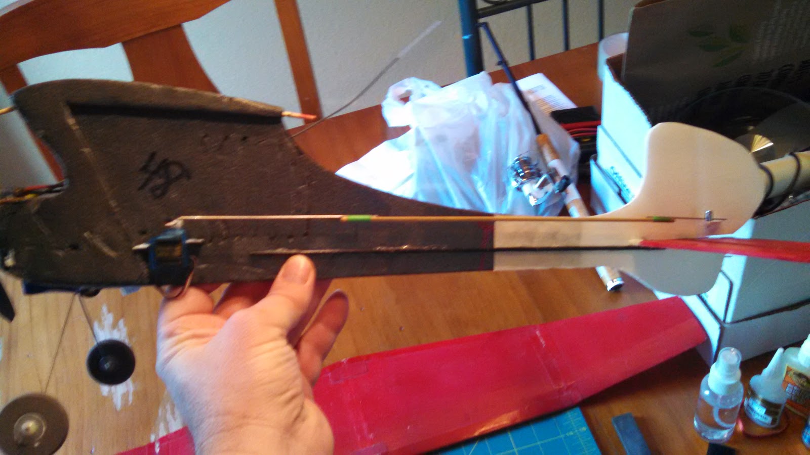
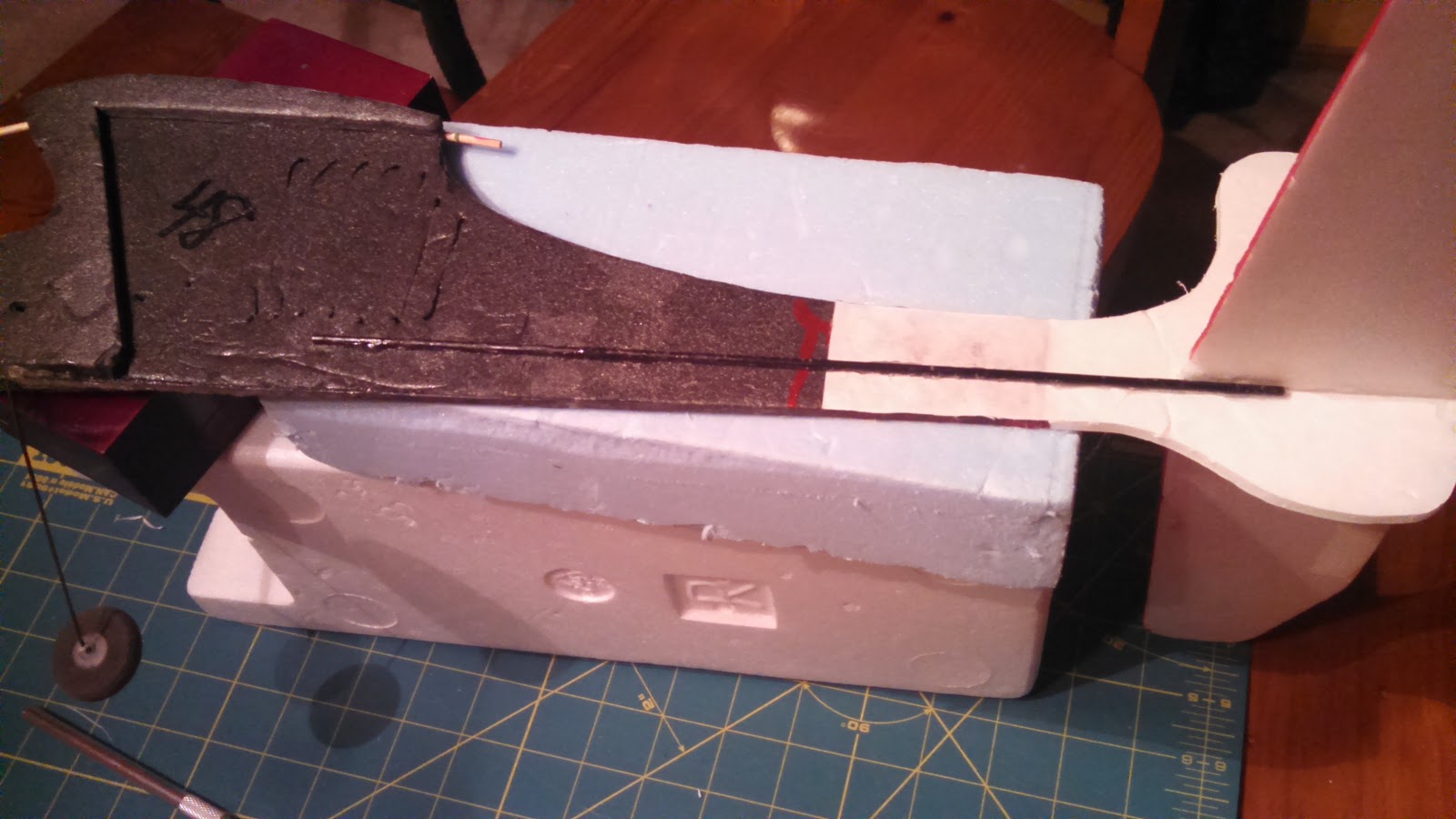
At this point, the carbon rod spar was glued back in place on the opposite side of where it was originally as this surface was clean and flat.  Instead of the brittle epoxy, I opted for Foam Tac which will be more flexible on top of being easier to use.

With the adding back of the carbon fiber spar, the frame reconstruction of this little plane is complete.

Now on to the control surfaces and electronics.

On the left in the photo below are the old servos that came with it.  They were a weird mix and I did not want to rely on them.  I happen to have two new 4g servos on hand and decided to swap them out.


Here is a photo showing the ESC and old servos again.  Note the micro connectors.


This photo shows the size difference in the connectors.  They are much smaller but I was not going to be able to use the 72MHz mircro receiver that came with it (I sold this receiver along with another on Ebay for about $20!).


Here is the new 4 channel receiver that I will be using with the two new micro servos installed.  The old ESC still has the micro connector.  I'll have to replace this connector as I don't want to replace this ESC as it already has all of the other connectors soldered on and I would have to get these as well.

OK, on to the tail surface repairs that I decided to make as well as changes to the control horn installs.

There were some dings in the leading edge of the stabilizer that I fixed by applying Gorilla glue and then covering with masking tape.  I let the glue foam up and then trimmed and sanded to shape.


I removed the elevator so that I could redo the hinge tape (pretty much rotted apart) and install a new control horn.  You can see here that the rudder just uses the paper on one side of the foam board for the hinge.

Here I'm cutting pieces from a plastic card to make the parts I need.  I kind of played with the shapes until I was satisfied.

I used this method (Ed from Experimental Airlines, thanks) where it glues on one side and penetrates to the other.  This makes for a light but solid horn.  I cant remember if I used hot glue or Foam Tac for this, but either should work well.  For the hinge on this piece I just use Scotch tape!  Works just fine for this little guy.


Here I did the same for the rudder making sure that at least one of the holes lined up with the hinge point.  You can see that it had to sweep forward to achieve this while not interfering with the cut out on the other side.


I did not want to just glue the servos to the side like had previously been done so I cut some strip of the plastic card and slid them through some slots in the fuse.  These were glued in with hot glue and provided perches for the servo tabs.  The servo tabs were then hot glued to these.  The photos below show both sides.


The push rods extend a long way and the old ones flexed a lot so I attached wires to the ends of some bamboo skewers to make fairly rigid replacements.


Here they are attached to both servos and control surfaces.  I used "Z" bends and mini "E/Z" connectors.  This made it much easier to make adjustments.


Here is a photo with all of the other electronics stuck on.  I used velcro for the receiver, ESC, and battery.  The battery is way forward so as to get the CG close.  It's still a little tail heavy.  As for the CG, I just kind of guessed assuming that it should be between 25 and 30% back from the leading edge.


This is what it look like with the wing balanced on.  I did not have a rubber band available, but this is what it looks like.


It's all ready to go now.  Just need a nice day and the battery charged.

I have since flown this little thing and I have to say that it is a real kick in the pants to fly.  Looks like it would be too light for any wind but surprisingly enough it handles the wind quite well.  I actually love taking this thing out and flying it when others won't because it's too windy.  One caveat is that it flies well once you get it nosed into the wind!  Otherwise your fighting to keep it from tumbling.  But hey, isn't that part of the fun!

Anyway, I hope this has inspired you to have fun with this hobby and to not be afraid of taking on what may seem like a piece of junk!

Thanks for stopping by my blog.  Please feel free to post comments, good or bad, and be sure to come back and check for future posts.

Monday, May 4, 2015

Foamy Rehab 1

Well, here we go!  Let's get started.

After looking over the whole aircraft and its design and parts, I decided that the ugly epoxy job had to go!  This really involved two items.  The first was the tail section where it had broken off just in front of the rudder.  The second was the carbon fiber rod that ran down the bottom of the fuselage.  Both were ugly globs of epoxy. 

This photo gives you an idea of the parts I started with.  Just imagine that the tail was still on and the electronics were also still installed, either on the white Velcro strip, or just in back of it.


This photo doesn't quite show it but if you look close you can see that the rudder does not line up with the fuse section.  It was off set and twisted.  My first thought was to just cut it somewhere and fix the alignment.  But I could not find a decent place to do that that would not involve sawing through epoxy.  I finally started by just breaking it off past the epoxy farthest from the tail.  This also involved separating some of the carbon fiber rod as well and you can kind of see that in the first photo and the next.

Next came an inspection of what was left.  I had this ugly jagetty edge and this long carbon rod to deal with.  I also was going to have to deal with this micro servo that was epoxied in as well.  I started by finding where I could cut a straight line and clean up the edge, which you can see in the following photos.  I did this so that I would have a clean edge to work with.

Now the carbon rod must come off!


The best way that I could figure out to remove the epoxy and carbon rod without doing too much damage was to carefully slide and work by Exacto knife between the foam and epoxy.  This took some time but worked surprisingly well!
All of the epoxy came off and did not do too much damage to the foam.  The worst area was toward the front, especially where the servo was.  No I was left with this ugly epoxy encrusted carbon fiber rod.  I was pretty happy with this so far.


The cheep Dutchman that I am, I just had to save that carbon fiber rod.  I started by breaking most of it off with my fingers.  Not such a good idea as some of it was sharp and pokey.  If you are going to try this, then I would suggest using gloves!  What did not come off with my fingers came off with using pliers to nip off pieces.  For the rest, I found that the biggest notch in my wire strippers fit over the rod just right and I started sliding it up and down to remove that rest.

I really did not like what was left of the tail and rudder section.  The elevator was just fine, but not the rudder.
I decided to come up with a replacement.  To make this, I laid out the pieces that I had and traced around them on a piece of Dollar Tree foam board.  I used this because it was very close in size to the depron that the rest was made from.  Then I cut this out and gave myself some extra toward the front.


In the following photos you can see how I cut out the foam from this extra length so that I could use the paper to help secure the two together.

This shows me aligning the two sections together.


This last photo shows how it will look when completed and glued.


Well, that's enough for now.  In the coming entries I'll complete this rebuild and hopefully give this plane a test flight.

Thanks for stopping by my blog.  Please feel free to post comments, good or bad, and be sure to come back and check for future posts.