Pages

Showing posts with label receiver. Show all posts

Wednesday, November 2, 2016

Foamy Rehab 2

Part II

At this point, the carbon rod spar was glued back in place on the opposite side of where it was originally as this surface was clean and flat.  Instead of the brittle epoxy, I opted for Foam Tac which will be more flexible on top of being easier to use.

With the adding back of the carbon fiber spar, the frame reconstruction of this little plane is complete.

Now on to the control surfaces and electronics.

On the left in the photo below are the old servos that came with it.  They were a weird mix and I did not want to rely on them.  I happen to have two new 4g servos on hand and decided to swap them out.


Here is a photo showing the ESC and old servos again.  Note the micro connectors.


This photo shows the size difference in the connectors.  They are much smaller but I was not going to be able to use the 72MHz mircro receiver that came with it (I sold this receiver along with another on Ebay for about $20!).


Here is the new 4 channel receiver that I will be using with the two new micro servos installed.  The old ESC still has the micro connector.  I'll have to replace this connector as I don't want to replace this ESC as it already has all of the other connectors soldered on and I would have to get these as well.

OK, on to the tail surface repairs that I decided to make as well as changes to the control horn installs.

There were some dings in the leading edge of the stabilizer that I fixed by applying Gorilla glue and then covering with masking tape.  I let the glue foam up and then trimmed and sanded to shape.


I removed the elevator so that I could redo the hinge tape (pretty much rotted apart) and install a new control horn.  You can see here that the rudder just uses the paper on one side of the foam board for the hinge.

Here I'm cutting pieces from a plastic card to make the parts I need.  I kind of played with the shapes until I was satisfied.

I used this method (Ed from Experimental Airlines, thanks) where it glues on one side and penetrates to the other.  This makes for a light but solid horn.  I cant remember if I used hot glue or Foam Tac for this, but either should work well.  For the hinge on this piece I just use Scotch tape!  Works just fine for this little guy.


Here I did the same for the rudder making sure that at least one of the holes lined up with the hinge point.  You can see that it had to sweep forward to achieve this while not interfering with the cut out on the other side.


I did not want to just glue the servos to the side like had previously been done so I cut some strip of the plastic card and slid them through some slots in the fuse.  These were glued in with hot glue and provided perches for the servo tabs.  The servo tabs were then hot glued to these.  The photos below show both sides.


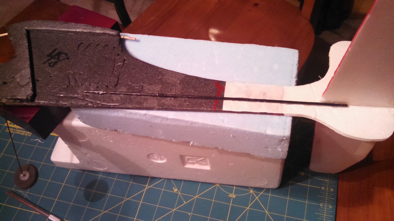
The push rods extend a long way and the old ones flexed a lot so I attached wires to the ends of some bamboo skewers to make fairly rigid replacements.


Here they are attached to both servos and control surfaces.  I used "Z" bends and mini "E/Z" connectors.  This made it much easier to make adjustments.


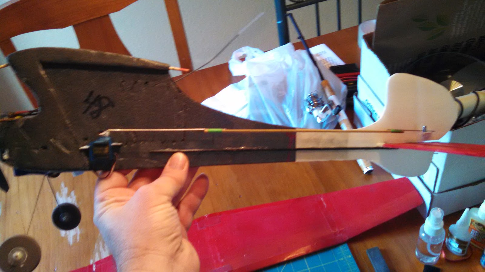
Here is a photo with all of the other electronics stuck on.  I used velcro for the receiver, ESC, and battery.  The battery is way forward so as to get the CG close.  It's still a little tail heavy.  As for the CG, I just kind of guessed assuming that it should be between 25 and 30% back from the leading edge.


This is what it look like with the wing balanced on.  I did not have a rubber band available, but this is what it looks like.


It's all ready to go now.  Just need a nice day and the battery charged.

I have since flown this little thing and I have to say that it is a real kick in the pants to fly.  Looks like it would be too light for any wind but surprisingly enough it handles the wind quite well.  I actually love taking this thing out and flying it when others won't because it's too windy.  One caveat is that it flies well once you get it nosed into the wind!  Otherwise your fighting to keep it from tumbling.  But hey, isn't that part of the fun!

Anyway, I hope this has inspired you to have fun with this hobby and to not be afraid of taking on what may seem like a piece of junk!

Thanks for stopping by my blog.  Please feel free to post comments, good or bad, and be sure to come back and check for future posts.

Tuesday, September 9, 2014

Trojan T28 Repair, Nose Gear Repair

From my last post you know that I have several repairs to complete on my Airfield/FMS Trojan T-28.  In this post I'll update you on how I repaired the nose gear strut.

The strut had a compound bend mostly back and to the side.  I have no idea how it bent this much without any damage to the plastic parts or the servo.

Any way, this is how it looked:


A big concern of mine was "how am I going to bend this back without breaking the thing?"  It really looks like any pressure on this thing is going to shatter any and all of that plastic.

My first thought was to use a bench vise and smash the thing straight again.  The big problem with that is that this method does not always come out completely straight and, worst of all, it most likely would leave lots of marks that would prevent free movement.

What else to do?  I thought about using a large pair of pliers or vice grips, but they tend to become unwieldy and would also most likely leave marks as well.

Needing some help, I browsed some forums for advice.  I did find one post that reported the same repair to their T-28 gear and they did use a vise, but only as a support to pry against.  They also mentioned that you could put a considerable amount of force on the plastic covered part without it breaking.  This sounded pretty good, but my vice isn't mounted down well enough to pry against (just sits on my bench).  So what next?

I was at work and thinking about where I might find something that I could insert the gear into that was sturdy and I could pry against.  This wasn't exactly what I was thinking of, but it's what I found.
I used my Excelite driver handle.  It worked great!  What I did was to hold the gear in my left hand and the Excelite screw driver handle in my right hand.  Then I used by thumbs to lever against the bent section.  Sorry but I did not get any photos or video of the process.  It did take some time as I took it slow, not wanting to over bend it or put too much force on the plastic.  I started with correcting one direction and got that straight and then worked on the other direction until it looked straight from both sides.

Soon, I had something that looked like this:

This was enough and it slipped right back into the trunnion of the gear servo without any issues.

After this I realized that I could have used any sort of pipe or tubing that was sturdy and long enough.  This sure seemed a lot better than using a couple of pliers.

So, with this resolved, I just had to take the landing gear servo apart and put it all back together with the strut back in place.

One down and how many to go?

Thanks for stopping by my blog.  Please feel free to post comments, good or bad, and be sure to come back and check for future posts.

Friday, July 12, 2013

T28 update and putting test equipment to good use

I really wanted to put my test equipment to use and I needed to check out my Airfield T28 with possible BEC/receiver/servo issues.  So I put it all together in this one big post.

This was a complicated subject with all the test equipment and airplane gear so I decided to try my hand at a video post.  So, here goes.


Thank you for watching my video post, let me know how you like this format.

Update to the video:

Further inspection showed that the faulty servo was not the steering servo but the door servo.  In the following photo you can see the bottom servo is the same servo that was over heating in the video.  You can also see that the push rod from the servo is flexed a lot.  This is obviously putting a lot of stress on the servo and is most likely the cause of the current draw.  Something will have to be done about this during the repair.

Stressed servo that failed

I have noticed that the current generation of the Airfield/FMS 1400mm Trojan T28 do not use a servo for these doors but instead uses spring linkage.  I may go this route for this repair and cut one servo from my count.

Thanks for stopping by my blog.  Please feel free to post comments, good or bad, and be sure to come back and check for future posts.


Saturday, June 29, 2013

Can't get enough test equipment

After a long hiatus, I am finally submitting a new post.

Since my last post I have learned a lot about RC equipment and testing.  This has led me to realize that I need another servo tester, or power analyzer.  This one does not control the server under test, but reports on the servo voltage and current use.  This is very important in making sure that servos are up to the task at hand and that the battery or BEC circuit is capable as well.

You may have seen one of my previous posts about my big T28 Trojan and my crash.  I suspected that this crash was due to power issues but have had no way to test this.  With this servo power analyzer I will be able to find out what is going on with the servo/receiver power system.

What is needed for this tester is a way to measure amps and voltage used by a servo, and all the way up to all servos including the receiver.

These are the parts that will be used build my servo power analyzer.


The parts consist of an amp meter, volt meter, project box, small circuit board, connector pins, and some connector lugs.  Also needed but not shown is some wire to make all of the connections.


This is a closer view of the Amp and Volt meters I used.  The Amp meter is rated at 5A max and the Volt meter has a rating of 10 volts.  Most of these testers that I have seen are setup for 500mA and 6 volts.  I chose these values so that I could monitor a larger range of current and voltage.


Another view of the inexpensive (about $6 each including shipping!) meters I bought on eBay.  These are inexpensive, but they'll do just fine.


This is a better view of how the circuit board and pins will be used.  The pins can be snapped off in the number needed.  Since these will be used for servo connections, these will be broken off in 3s.  The circuit board will be cut in half and one half used for each end.


This is how the completed tester looks with the two meters mounted on the face.  The connectors are on each end.


These are the pins for the output or servo side.  I opted to provide two connectors here so I could hook up two servos at a time.  I could also use a splitter cable as well but this was easy enough to add.


This is the input side (sorry for the blurry photo).  There is no need for more than one input here.


This shows a typical setup for testing a servo.  With this setup I can monitor any voltage and current fluctuations while the servo is put through its paces.

The way I plan on using this to test my T28 setup, is to plug the BEC into the input side and the receiver with all of the servo connections into the output side.  Then I will monitor for voltage fluctuations (anything dropping much below 6V) and maximum amp flow.  Anything above the amp rating of the BEC will be a sign that it is not up to the task or I have a problem with a servo or two.

I realize that I did not include a circuit diagram and this would be very helpful for anyone wanting to make one of these.  It's really very basic and should be easy to duplicate.  So, here it is:


The positive voltage path flows through the Amp meter.  The voltage is measured the positive and negative voltage paths.  The servo signal wire passes straight through without interruption.

Thanks for stopping by my blog.  Please feel free to post comments, good or bad, and be sure to come back and check for future posts.

Friday, March 30, 2012

Using A Servo Tester

OK, so now admit it, how many times have you installed a servo and hooked up linkage, assuming that it was centered, only to find out it was not.  Come on, admit it, all of you have done this at one time.  Why have we done this?  Because we are all too lazy to hook everything up to a receiver and battery and to power on a transmitter.  That's why you need a servo tester.

This is the Turnigy servo tester that I found and purchased.


You can connect up to 3 servos and test them all at the same time.  There are three settings that are cycled through by the press of a button.  The default when powered up is the manual dial.  Press the button and it goes to center.  Another press of the button and now it cycles from one end to the other and will continue until you change the setting or run out of battery.  To power this little guy I purchased a 4x AA battery holder from Radio Shack and added a servo connector.  I have also used this device to test speed controllers and retractable landing gear.  For testing an ESC, no battery is needed if it has an included BEC.

The only draw back is that the LED is way too bright and blinding if you're not careful.

Here is a video showing this device in action.


For about $6 you just cannot go wrong with one of these and it's a must for any toolbox.

Thanks for stopping by my blog.  Please feel free to post comments, good or bad, and be sure to come back and check for future posts.


Thursday, January 5, 2012

Flapperons

Hello all,

Since I now have a programmable transmitter and an airplane with ailerons in need of flaps, I decided to see what it would take to setup flapperons.  My initial installation of ailerons consisted of flaps cut into each wing with servo to operate each one and a "Y" cable to connect both servos to channel one on the receiver.  One servo was installed apposed to the first one so that they in effect move opposite of each other.  This proved to be a perfectly usable way to run ailerons and is easy to trim.  As there is no room to add flaps with another set of servos, it seemed reasonable to try setting up mixing to accomplish this.

Cutting out the Y adapter

Both connectors cut out


New aileron extensions installed
The first thing I needed to do was to cut out the "Y" cable that I had glued in.  Each of the split connectors were glued, one into a cutout in each side of the fuselage.  Once these were removed I replaced them with regular extensions.  One of these would go into channel 1 and the other would go into channel 6.  Channel 1 would then be mixed with channel 6 and channel 6 set for reverse direction.  Then switch B would be mixed with channel 1 and then again with channel 6.  Since channel 6 had been reversed for aileron control the mixing of switch B would also need to be reversed.


HK T6A V2 6 channel transmitter
As I have a Hobby King T6A V2 2.4GHz 6 Channel transmitter, this required the use of the T6Config software.  Now I have to say that this isn't the greatest software but it is functional.  The first time I used it, it worked just fine and I was able to reverse my elevator servo and play with a few other settings.  Well, that was some time ago and I have not needed it since.  This time when I started up the software I was unable to get the software to work with the programming cable.  Each time I selected the com port (4 in this case, oh, and even though this is a USB cable, it appears as a serial connection) the software would freeze up.  I suspect this is due to software updates that have broken the old driver.  It took a while but I was finally able to find the link to the USB cable site and download the latest driver.  With this new driver all was working fine again.

On to the software settings.  The following show the actual settings used to accomplish the mixing that I  mentioned above.
Mix 1 causing channel 6 to follow channel 1
Mix 2 adding channel 1 to switch B
Mix 3 adding channel 6 to switch B 
There are others who have rate settings for mix 2 and 3 set as low as 10 and as high as 75.  I thought I would use 50% so as  to give more room for experimenting.  In this case, 50% gives 50% down when applied and still leaves another 50% of down for ailerons.  Note also that mix 3 is -50% as this servo is reversed for aileron control.  Also note that with this particular transmitter, as the dials are associated with the switches, VR B will also affect the amount of flaps (adjust how much of the 50% is applied).  Just as a side note, my channel 5 is switch A, and I left that setup as a throttle cut off.  This is a whole other story as to how well that works with a stick programmable brushless speed controller.

In testing, all of this worked as planned!  Unbelievable that it worked on the first try.  This seems to never happen for me.  I am a happy camper.

Flapperon testing

So, now it's off to see how it flies!

Thanks for stopping by my blog.  Please feel free to post comments, good or bad, and be sure to come back and check for future posts.

Wednesday, December 14, 2011

Plane Video

Hello all,


I don’t know how many of you know this, but I’m a cheap penny pinching Dutchman.  I’m always looking for the cheapest way to do something.  I’ll spend $25 dollars in gas driving around to find something $20 cheaper!  This doesn't exactly fit with my passion for technology or invention as both usually mean spending money.  Why am I letting you know this?  Well I’m back into this whole radio control flying thing and I got really excited about the prospect of taking video from the plane.  I’ve done the video thing of the plane in flight (I even took some video of my plane while I was flying when I couldn’t get someone to come along) and that’s good and all and I won’t stop doing this, but I would really like to add video from the plane.

I started looking into the options available.  I could go with a standard video camera but they are way too big for the size of planes I am currently flying.  Also most of these still use some sort of media to deal with (disk or tape).  Digital cameras can be used and most are very small now, but they are still to big and or to block shaped.  The next option I looked into were specialty DVR systems.  While very cool and packing a lot of features, these are way too expensive and some still require the addition of a camera.  The last option I found out about was the use of a cell phone that has a camera with a video option.  As I am cheap and because I have a few old cell phones laying around, this is the option that I am starting with.

Camera side of LG phone
Of all of the phones that I have available, the only one that is going to work for my needs is an LG Vu960.  This is a relatively flat card deck size touch screen phone.  This should allow for a fairly aerodynamic option if I can keep it flat to a surface on the plane.

Screen cover removed and connections exposed
Well of course things are not going to go well.  The reasons I selected this phone is because it was the only one that I had that has all of its parts and was still working.  Almost working.  Turns out the touch screen was having issues and touching some parts of the screen produced no results and were dead spots.  And as expected, these dead spots were over the selections for starting video recording and settings.  After some searching with Google, I found out that this is not an uncommon issue with this phone and can sometimes be resolved with pealing off the glued on screen cover.  This exposed the touch screen sensor connections and made the phone functional.  Now if I come across an area that does not respond I just hold down on the connectors and it responds again.

Cell phone taped into position
Well I figured I was all set and I could just tape the phone to the plane.  The location I selected was the bottom side of the left wing (port or starboard, I don't know).  This should work well while testing and if I like this set up I can look at changing over to Velcro.

This all looked like it was going to work just fine and so it was just a matter of finding time to try everything out.

The day came when my schedule allowed some time to fly and the weather complied.  I was excited to get into the air as the day was calm with some low overcast.  I was hoping to get some video from the clouds!  I got out to the field and hurriedly put everything together, turned on my radio and  receiver, tested the controls, and tossed the plane into the air (I did not have any landing gear on this plane at this time).  I had a wonderful flight and, and, got up into the clouds!  I was so excited to get the plane back and look at what i had videoed!

I hurriedly got the plane down and ripped of the tape to get to the phone.  I was very disappointed to find out the the video had stopped!  Not only had it stopped, but only recorded 43 seconds!  What's up with that.  I set the phone to record to test it out.  It only recorded 43 seconds again.  What?  Oh man, back to Google.

So what did I find out?  Something simple of course!  As with all phones that can record video and send them attached to text messages, they limit the video size.  All I had to do was to reset this option and now I can record for as long as I have memory.  While I was at this, I also made sure that the phone was set to record video directly to the SD card.  This makes transferring video much easier as I don't have a USB cable for this phone and don't want to deal with Bluetooth.  Oh, while I'm relating the cell phone settings, I also put the phone into, appropriately enough "airplane mode".  This turns off the cell phone connection.

OK, I waited for another opportunity to fly.  I got that opportunity and made a few good videos that covered the entire flight!  These were fine, but the camera is facing directly down and so while most of it has interesting views of the surroundings, these videos can be quite nauseating.  I need to find some way of getting a view that looks forward.

Mirror and foam pieces

So how am I going to change the view?  My daughter suggested just taping it on somewhere (the cockpit) facing up but that just makes it this big flat surface pushing through the air.  I figured there must be a better way of doing this.  I decided to try using a mirror to get a view forward.  I checkout out my local Micheal's store and found some small mirrors.  Then I cut out some foam pieces that will help me to mount the mirror at an angle to the camera lens.  After some testing I realized that the phone would have to sit sideways to get the wide angle view the camera was intended to have.  This presented another issue in that the way I was going to set it up, would give me a video that scrolled from bottom up instead of top down.  This meant resetting the mirror again.
Mirror attached
Back side of mirror and foam bracket
You can see from the included pictures that I just hot glued everything together.  This works very well and make it easy to change things if needed without damaging the phone.  Now all is setup and ready for testing again.

I finally had a chance to fly again and took some really fun videos of flying my plane for the first time with the landing gear installed (see my other blog My Wild Hawk Experience for more on this).  Well, one final issue with this.  I noticed that there was something wrong with these latest videos.  The right and left are swapped such that if the plane goes left, the video shows it going right!  Oh well, what can I expect for my free kludged solution.

The latest update on this story is that I gave in and ordered a video recorder from my favorite hobby site Hobby King.  They have a video recorder, that looks like a car remote key fob, for less that $10!  Even as cheap as I am, I can't pass this up.  As usual something always goes wrong for me and this is no on back order!  Oh well, Ill post again when it comes in and I get a chance to test it out.

As usual, join my site, make a comment, and don't forget to come back for more.


VNHDTVDCK6NV